Pitch is the speed at which the cutting head moves from the outer edge toward the center of the lacquer during the cutting process.
This parameter is expressed in R/mm (grooves per mm) in Europe and in LPI (lines per inch) in English-speaking countries.
The suspension box, which houses the cutting head — visible in the upper right corner of the photo above — contains several electromechanical mechanisms that allow control over the groove’s base depth, stylus heating, head lift, etc.
The head/suspension assembly moves because it is guided by a worm screw, which is driven by a variable-speed motor. In older cutting systems, there is sometimes a second motor — activated by contacts opened or closed by micro-switches positioned at certain diameters, or by buttons — which handles fast travel functions such as the lead-in spiral, lead-out spiral, and the visible spacing between tracks. In more modern systems, a single motor handles everything.
In any case, the space between grooves during cutting always depends on the rotation speed of the pitch motor.
In the simplest case, the pitch can be set to a fixed value. There are tables and formulas that determine its relationship with cutting duration and rotation speed.
A commonly used formula is the following:

The term “dec” refers to fractions of a minute, which must obviously be considered on a decimal basis. The value of r is discretionary and essentially depends on how far from the label you want the cut to end.
To calculate r, keep in mind that the diameter of the disc is 300 mm, which divided by 2 gives a radius of 150 mm. From this value, you subtract half the space occupied by the label (100 mm / 2 = 50 mm), the (fixed) space taken up by the lead-in spiral, and the (discretionary) space taken up by the lead-out spiral. The visual gaps between tracks are usually considered negligible.
A plausible value for r could be: 150 (diameter / 2) - 50 (label / 2) - 5 (lead-in spiral) - 10 (lead-out spiral) = 85 mm.
For example, if you want to cut a side that lasts 20 minutes and 30 seconds, the grooves per mm would be: 20.5 × 33.33 / 85 = 8.03 R/mm.
The base groove width (i.e., unmodulated by the signal) is typically adjusted with a potentiometer, which sets the base current supplied to the head’s moving coils. Usually, this adjustment is made empirically by cutting silent grooves with the pitch already set to the desired value.
However, groove width can also be calculated: continuing with the previous example, since there are 8.03 grooves per mm and 1 µm = 0.001 mm, assuming a 10 µm gap (land) between grooves, the theoretical maximum width would be just under 115 µm.
It’s clear, though, that this calculation does not take into account the vertical and lateral excursions of the stylus, which — as previously discussed — are determined by the characteristics of the signal being cut.
In the case of a 45 rpm 7 inch record, a discomix, or any other scenario where the cut is relatively short, using a fixed and wide pitch (5 R/mm or less) is almost always feasible without having to worry much about such excursions. There is, in fact, a limit to the cutting volume, beyond which issues such as excessive groove curvature arise, as previously mentioned. So generally, one avoids exceeding a certain volume (typically 0 to +3 dBVU, max).
And with very wide pitch values (4 or 3 R/mm), even at such high volumes, groove collisions are unlikely. Problems might arise only in the case of very low frequencies (see the time constants discussed earlier) cut at peak volumes as mentioned above — but even then, it is rare.
Using fixed pitch provides “geometric” certainty about how the cut will turn out. But almost always, precisely to avoid the risk of overcuts, cutting volume is slightly sacrificed, and as a result, so is the signal-to-noise ratio.
It can therefore be said that for cuts lasting more than 15 minutes, fixed pitch — unless strictly necessary — is never a good choice.
In the case of long-duration LPs with some dynamic range, it’s desirable to reduce the spacing between grooves whenever the stylus’s horizontal excursion — due to lower signal amplitude and/or fewer low frequencies — allows it.
The space saved in all those sections can be used to cut at a slightly higher volume, or to end the cut within a smaller r, meaning farther from the label, where peripheral speed is higher.
With pitch and depth control, the “R/mm” parameter becomes dynamic, continuously changing based on the signal’s amplitude and frequency content. By simulating the cut and observing the R/mm values generated by the signal at various points, you can adjust the volume so that the average R/mm roughly corresponds to the value you would get using the earlier formula. In most cases, the volume will be +2/+3 dB higher than with the same cut done using fixed pitch. In special cases, the gain in dB can be even greater.
Functions of Pitch and Depth Control
The Pitch and Depth Control:
- dynamically adjusts the pitch, based on the content of the signal;
- dynamically adjusts the groove depth (which also affects the horizontal space occupied by a groove, and therefore must be considered in the previous point);
- can ensure that the groove depth does not fall below the traceability limit (usually 30µ), by correcting the vertical excursion of the stylus;
- prevents overlapping of adjacent grooves;
- maintains a constant minimum spacing between the outer edges of adjacent grooves (called land).
The Pitch and Depth Control requires a twin signal of the one being sent to the cutting head. This is because it must store and process some data about the signal a short time before it is cut onto the lacquer.
Therefore, the signal that is actually sent to the cutting head (and cut into the lacquer) is delayed by a fraction of a second (depending on the system used and the cutting speed), while the signal the Pitch & Depth Control receives in real-time is called the preview signal.
Each revolution of the lacquer is divided into sectors, and each sector is associated with a memory space, which can be digital or analog.
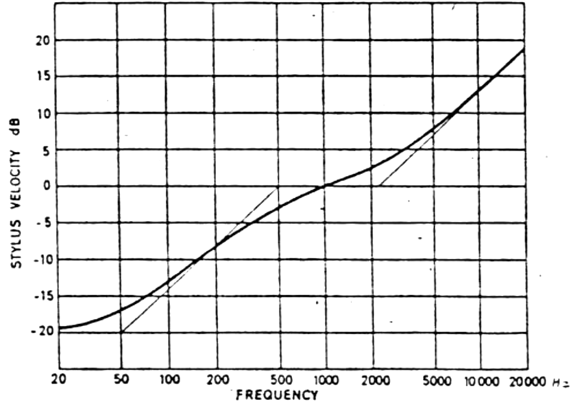
In both cases, the data to be stored relates to the left and right channels of the preview signal, previously equalized with the RIAA curve, which is also applied to the twin signal that is sent to the cutting head a short moment later. The diagram below¹ shows the input filter of a Pitch & Depth Control system, which essentially mirrors what has already been discussed regarding RIAA equalization.
The “sector” is the time interval during which the system gathers audio information from the preview signal and interprets it as data for lateral modulation and depth. Zero is the center line (i.e., the bottom) of the groove, and ”+” signs indicate the positive polarities of the left and right channels.
The few microns of empty space between the outermost horizontal excursions of two adjacent grooves (outlined in the diagram by dashed lines to the left of L and to the right of R) are the land.
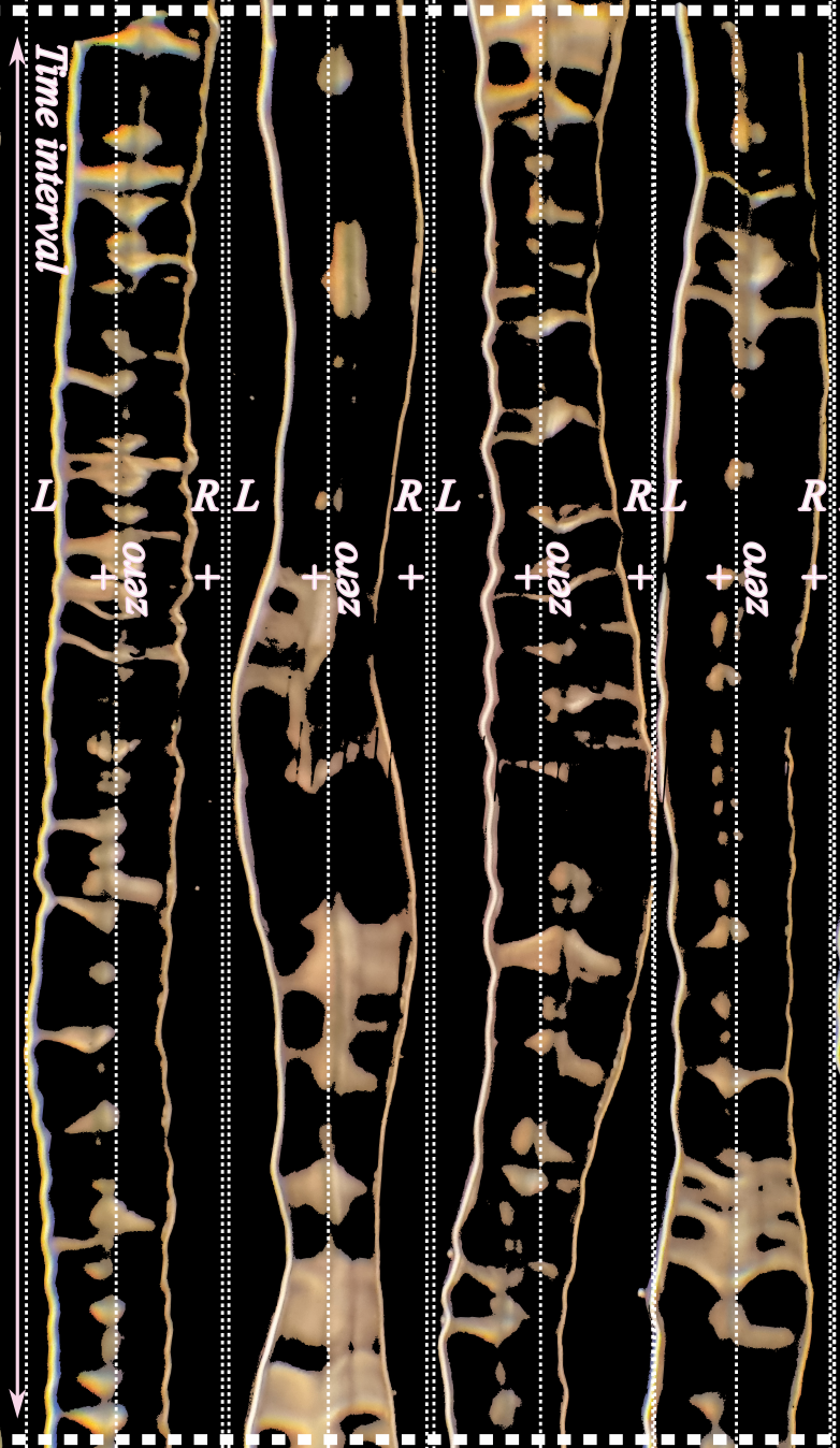
Since cutting proceeds from right to left (i.e., toward the center of the disc), the system considers the left channel (L) of the previous groove and the right channel (R) of the next groove. The goal is to move the cutting head just enough so that the edges of the two adjacent grooves barely touch at the point of maximum lateral excursion within that sector — also accounting for the horizontal component due to any changes in depth, plus a land spacing which may range from zero to any desired number of µm, as chosen by the operator.
From the preview signal, the system continuously detects and stores the following voltages:
- L- (lateral excursion)
- R+ (lateral excursion)
- (L+) - (R-) (depth)
Once these values are stored, the system sums the following voltages:
- max(L-), stored from the previous rotation
- max(R+), from the current rotation
- (max(L+) - R-)/2, stored from the previous rotation
- (max(L+) - R-)/2, from the current rotation
The sum provides an index, which serves as the starting point for increasing or decreasing the duty cycle of the PWM that controls the motor’s movement during the time interval corresponding to that sector. The current values of L+, L-, R+, and R- are also stored to be used during the next rotation.
The implementation of all the above can be carried out either in the purely analog domain or in a hybrid analog/digital system.
Due to the high precision required — especially in fully analog systems — it is common practice to insert trimmers at certain critical points. These allow for fine adjustments using test signals during setup and, if necessary, real-time corrections during operation.
Permissible and Non-Permissible Overcuts
With Pitch and Depth Control, the centers of the grooves are always spaced correctly. However, in certain situations (excessive depth or widening, high volumes, sharp curves, or no land), it may happen that part of one side of a groove is cut on top of a more or less significant portion of the adjacent side of another groove.
This does not always cause playback issues. To understand what can happen, one must consider the tip radius of the playback stylus (commonly 15µ) and compare it to the width of the two adjacent grooves at the point where they overlap.
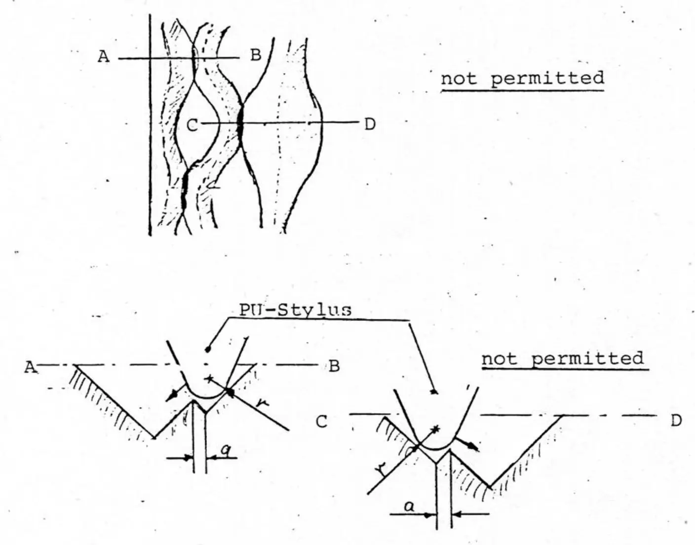
In the previous diagram², we see the worst-case scenario. Here, there is negative land, which results in a slight overlap between grooves at points of maximum lateral excursion. In both segments AB and CD, this overlap can cause problems when reading the narrower groove, because one of its walls has been partially erased by the cutting of the adjacent groove. As a result, the playback stylus cannot sit properly at the bottom of the groove, which will lead to distortion or even a skip during playback.
If we call a the width of the groove wall, and r the tip radius of the playback stylus, in this case we have a < r.
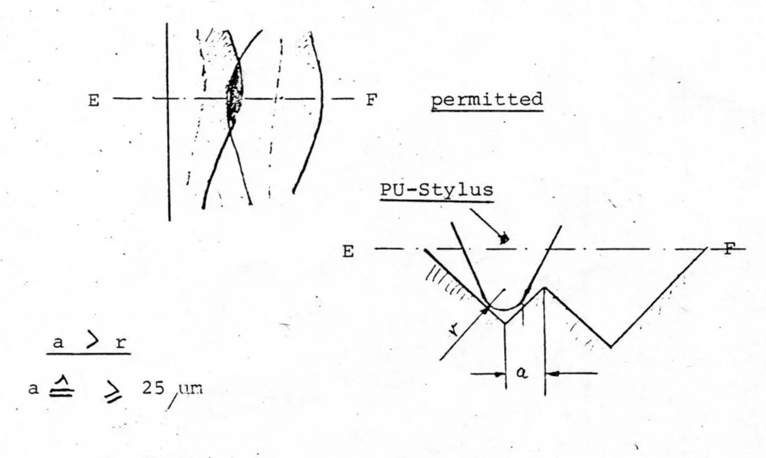
In the diagram above³, however, a similar overcut occurs between two much wider adjacent grooves, which — despite their partial overlap — still provide ample space to allow the stylus to sit correctly. Therefore, playback is not affected.
¹ ² ³ Struck, Polygram Pitch Control IV user manual, internal files, UK-Europe 1977-82