Although a complete cutting system can be complex and comprising numerous components, its fundamental elements are few:
-
audio source;
-
monitoring and cutting amplifiers, the latter supplying current to the two coils of the cutterhead;
-
cutterhead, which vibrates the cutting stylus, generating the depth and the geometry of the grooves;
-
lathe, responsible for the cutterhead’s movement along the recording radius, the turntable’s rotation, the suction of the chip off the lacquerdisc’s surface, groove spacing and various automatic and semi-automatic functions;
- master lacquer and cutting stylus, the latter made from a hard industrial stone (such as sapphire, ruby or diamond), specifically faceted with a tip which -- when new -- has a diameter of just a few micrometers.
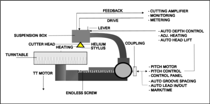
The cutting process begins with amplifying the line signal through the cutting amplifier, which supplies current to the two coils of the cutterhead (one coil per channel).
The inductance of the coils generates a small electromotive force via transducers, causing the stylus to vibrate and etch the modulation grooves onto the lacquerdisc.
The power required by the amplifier for such applications is significant, though in theory, it is lower than the power used today in many modern cutting amplifiers (typically between 400 and 600W per channel). Much of this depends on the magnetic characteristics of the cutterhead. Over the years, cutterheads have evolved in terms of materials, requiring progressively less wattage to produce the same dB of signal.
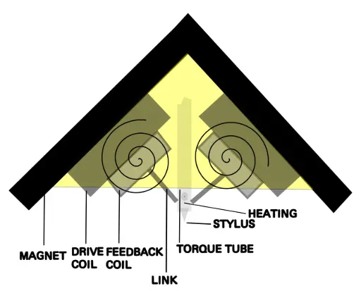
The head and the feedback circuit
The following figure illustrates the basic components of a cutterhead, including the main coils and feedback coils (signal return). The spirals depicted in the figure are not actual components but simply represent the presence of a magnetic field.
The cutting process can be briefly summarized as follows:
- the line signal is a voltage modulation in an alternate current (AC) regime. Up to the cutting amplifier, the circulating current is relatively low;
- the cutting amplifier is the main "load" of the system. As mentioned, it supplies the current to the cutterhead’s coils based on the modulated voltage. It is typically equipped with a circuit breaker per channel to interrupt the current flow before it reaches the cutter head in case of overload;
- when the coils receive current, they generate inductance;
- the cutting stylus is moved by the small force generated by the combined magnetic fields of the two coils. The transducers consist of two links positioned 90° to each other, similar to the coils. The cutting stylus itself is mounted in a torque tube located at the centre of this 90° angle;
- assuming the stylus is lightly touching the lacquerdisc’s surface and the disc is rotating at a constant speed, the stylus vibrations will be transferred to the surface, forming grooves.
If the cutting system is equipped with a feedback circuit, two smaller feedback coils are positioned at the base of the two drive coils. These capture the signal generated by the main coils and return it to the amplification and monitoring sections.
The feedback circuit was first introduced in 1947 on cartridges from three models: Presto, Fairchild, and Cook, to ensure a linear frequency response.
Over the years, it has been observed that each stylus, based on its construction characteristics, generates a resonance peak around a specific frequency. Therefore, before the signal is recorded onto the master lacquer, it must be corrected to cancel out this peak.
The correction of the resonant frequency through the feedback circuit is achieved by summing an additional signal that is filtered both above and below the resonant frequency, with a phase opposite to that of the main recording signal.
As is well known, the sum of two equal line, single-frequency signals with opposite phase results in zero, provided the amplitudes are the same. If the amplitudes differ, the resulting signal will still be attenuated. This requires manual adjustment of the levels of the two signals until the desired dB correction is achieved, resulting in a flat-frequency response.
The methods and specific parameters may vary between heads and cutting systems.
1 “An Audio Timeline” - AES.org. Audio Engineering Society, USA 2023
The Lacquercut Process