The essential elements of a phonographic recording system are:
- audio source (line signal);
- master disc for cutting, consisting of an aluminium core coated with a type of nitrocellulose-based paint, oils and other additives;
- RIAA equalization circuit;
- amplifiers (for cutting and monitoring);
- cutterhead, to which the cutting stylus is attached, a hard stone for industrial use (sapphire, ruby, diamond), appropriately faceted, with a tip of a few thousandths of a mm (this unit of measurement, which we will often use from now on, is called "micron" and is expressed by the Greek letter µ);
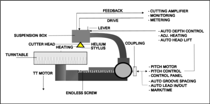
- electromechanical lathe, responsible for:
- movement of the cutting head along the cutting radius;
- turntable rotation;
- suction of the chip removed from the surface of the master disc;
- spacing of the grooves;
- other automatic and semi-automatic functions.
The cutting process first goes through RIAA equalisation. Without it, the vibrations of the cutting stylus would produce grooves with an amplitude and geometry that would be practically impossible to trace. However, explaining why RIAA equalisation is necessary requires a more in-depth discussion, which we will return to later.
The modified signal is then strongly amplified by the cutting amplifier, which is connected to the two coils of the head (one coil per channel).
The inductance of the coils generates, through transducers, a small electromotive force that makes the stylus vibrate. If the cutterhead is lowered and thus the stylus touches the master disc, which is meanwhile spinning, these vibrations are engraved in the form of grooves.
With the reverse process, therefore following the grooves with a playback stylus, applying the inverse RIAA equalisation to the electrical signal generated by the coils connected to it, and amplifying the re-equalised signal, we will be able to listen again to the line signal that has been recorded.
The cutting amplifier must be powerful enough to make the stylus vibrate appreciably, somewhat like what would happen with a speaker's tweeter. Much also depends on the electromagnetic characteristics of the cartridge: over the years, cartridges have evolved in terms of materials, requiring less and less wattage to produce the same dB of signal.
The head and the feedback circuit
The following figure illustrates the basic components of a cutterhead, including the main coils and feedback coils (signal return). The spirals depicted in the figure are not actual components but simply represent the presence of a magnetic field.
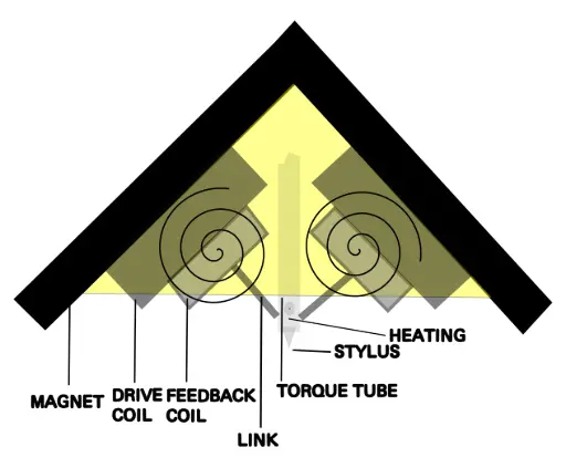
In addition to the links and the torque tube, elements that perform the mechanical task of transmitting the electromotive force from the drive coils to the stylus, we can also note the presence of the heating of the cutting stylus.
This is a simple circuit that provides direct current, at a certain adjustable and constant intensity, to a copper filament that is "wrapped" around the top of the cutting stylus. Its function is to heat it, reduce the friction during cutting, and consequently also the background noise (which in this case is called hiss noise). However, one must be careful, as too much heat can weaken the stone and hinder the chip suction.
In fact, the freshly cut grooves cannot remain on the surface of the master disc. This is precisely why there is a small suction tube close to the engraving stylus. We can observe it in the first photo above. The vacuum is usually provided by a pump located outside the room where the cutting system is situated.
Finally, we note the presence of the feedback coils. Not all cutting systems are equipped with a feedback circuit, which is very important for monitoring the signal as it arrives at the cutter head.
But the function of the feedback circuit is not only that. Introduced for the first time in 1947 on cutter heads of 3 different models (Presto, Fairchild, and Cook), it primarily serves to ensure that the frequency response of the cutter head is linear.
In fact, over the years it has been observed that each stylus, based on its construction characteristics, generates a resonance peak around a certain frequency. Therefore, the signal, before being actually recorded onto the master lacquer, must be processed in such a way as to cancel both the main resonance and its harmonic frequencies.
The correction of the resonant frequency through the feedback circuit is carried out — in professional systems — without RIAA equalisation. To the recording signal, the same filtered signal is added, in inverted phase, both above and below the resonant frequency. The attenuation level of this signal must be adjusted to a certain number of dB, according to the recommendations of the cutter head's manufacturer.
To be precise, the adjustment must be repeated several times, given the many components involved. Once the dB of the resonant frequency have been attenuated, the RIAA equalisation is reintroduced and the frequency spectra of the input signal and the feedback signal are compared, for example using pink noise.
These adjustments naturally impact both the level and the balance of the two channels. Once the frequency response of the two channels is satisfactory, the amount of current that the cutting amplifier provides to the drive coils of the cutting head must be adjusted, until the recorded signal (usually, for convenience, a sine wave at a frequency of 1kHz at 0dBVU is recorded) corresponds, upon playback, to the same signal from a reference disc (there are several available on the market).
The methods and specific parameters may vary between cutter heads and cutting systems.