Despite the fact that in the 1980s and 1990s there was a period during which even vinyl records — in some plants — were produced by injection moulding, their manufacturing normally involves the classic pressing by compression.
The presses for pressing records therefore squeeze the PVC disc created by the extruder by exerting their force in a vertical direction, almost always from bottom to top, and this force propagates outwards in a uniform manner.
This is made possible by:
- a three-phase electric motor;
- a dense fluid (oil);
- a pump that moves the oil and keeps it pressurised.
The maximum force F with which the press squeezes this disc can be quantified as the product of the area over which the force is applied and the pressure. What exerts the pressure is a pressurised fluid, namely the oil, while the area is the circular section of the cylinder in which the oil itself is contained.
Since the area of the circle is given by the square of the radius multiplied by π, the force F is defined as:

where P is the maximum pressure exerted by the oil in the cylinder during compression and r is the radius of the cylinder.
For example, with a cylinder whose circular section is 25cm² and with a maximum pressure of 200bar, we have:

substituting,

The figure below illustrates a simplified hydraulic circuit, in which only the main elements are represented, in order to make its operation understandable. The same circuit, in reality, would be a bit more complex, including pressure switches, non-return valves, transducers, etc.
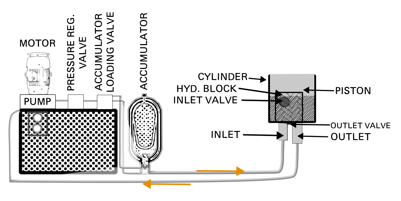
The operating principle is as follows:
- the pump circulates the oil from the tank to the hydraulic block of the press (orange arrow to the right);
- when the dump valve is open (outlet valve), the oil flows back into the tank (orange arrow pointing left);
- when the logical control unit of the press opens the oil inlet valve and closes the outlet valve, the oil enters the cylinder of the press;
- when there is enough oil, the piston pushes upwards the platform on which the lower mould is mounted;
- when the lower mould and the upper mould meet, the piston continues to push, increasing the oil pressure in the cylinder and first generating the expansion of the PVC disc outwards, then its gradual compression inside the moulds;
- the oil pressure inside the cylinder rises until it equals that of the circuit;
- meanwhile, the injection of steam inside the moulds brings them to a temperature close to that corresponding to the steam pressure at that moment, let‘s assume around 180°C; the PVC in contact with them then becomes fluid and malleable, making it possible to imprint the grooves present on the stampers onto the PVC;
- with the oil drain still closed, and therefore at maximum pressure, the steam inlet and condensed steam outlet valves close, and the cooling water inlet and outlet valves open. The disc then cools and becomes plastic, meaning it takes on a morphology that is no longer subject to large variations at room temperatures (even though — as we will see — the complete thermal stabilisation of the disc takes several hours to complete);
- throughout this process, the oil pressure in the circuit remains constant thanks to a pressure regulating valve.
It is important that the press closes within a few seconds, also to prevent the PVC disc from losing some of the heat previously accumulated in the extruder. Therefore, at a point in the oil circuit, energy must be stored that can be released quickly, so as to move a large volume of oil in a short time.
To meet this requirement, accumulators are used, which take advantage of the high compressibility of gases compared to liquids. Their frame is made of forged stainless steel to withstand high pressures, and there are two different types:
- Bladder accumulators
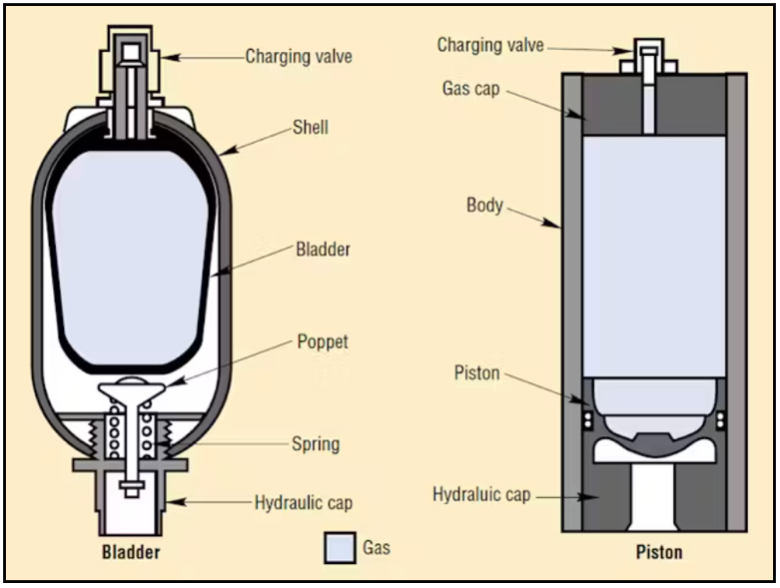
In this type of accumulators:
- an elastic membrane separates the upper section (filled with gas) from the lower section (where the oil circulating in the circuit enters);
- the oil circuit is connected to the bottom of the accumulator;
- when the accumulator pressure (Pa) and the circuit pressure (Pc) meet:
- If Pc > Pa, the oil enters the accumulator until the two pressures equalise;
- when the oil inlet valve opens, the compressed gas expands and pushes all the oil present in the accumulator into the press, at a speed much higher than that achievable with the pump of the circuit;
- since the oil pressure into the accumulator has meanwhile decreased, the gas is free to expand again into the membrane, returning to the initial condition;
- a bottom valve protects the membrane from accidental damages, in the event that the accumulator runs out of oil.
2. Piston accumulators
Their operation is similar, with the difference that in this case the expansion of the gas in the upper part compresses a piston that contains the oil coming from the circuit.
The gas commonly used in accumulators is nitrogen, an inert and readily available gas.
Typically, the flow of oil pushed by the accumulator runs out just before the complete closing of the press is completed, so that during the last few millimetres of the piston stroke and during the compression, only the flow of oil produced by the pump reaches the cylinder. This allows the accumulator to recharge and ensures the final pressing phase — the one in which the PVC disc is in contact with the grooves on the moulds — to be more accurate, at low speed, high pressure, and synchronisable with the thermal cycle with better accuracy.
The oil pressures typically used are:
- 60-70 bar for fast approach;
- 180-200 bar for the final squeeze.
Even when the oil has completely drained from the cylinder of the press, a bit of force is needed to constantly push downwards to lower the press plate to the same point each time.
This function is performed by small return cylinders or, in older presses, by return springs.
The return cylinders are constantly under pressure, both when the press is closed and when it is open, and they always exert a force of a few tonnes pushing the press plate downwards. When their force becomes greater than that of the main ram, the press plate descends completely.
Similarly, the return springs are compressed when the press rises and release the accumulated energy, causing the piston to descend, when they overcome the oil pressure following the opening of the drain.
As mentioned earlier, actual hydraulic circuits are a bit more complex than the simplified model just discussed. The additional elements include:
- dual pressure systems, with one motor, two pumps and separate valves for the entry of a low-pressure flow and a high-pressure flow;
- non-return valves: they prevent backflows and different pressures from mixing at critical points;
- pressure switches: control the flow of oil based on pressure readings at specific points;
- centralised circuits: in some installations, a single large motor with a pump is used, along with several accumulators to supply all presses, eliminating the individual hydraulic units that usually accompany each press.